electrical network
Tags: #definition
electrical network
We shall treat an electrical network as a weighted graph
- vertices are labelled
through with being the voltage source and is the ground (so there is a battery connected to them completing the circuit) - the weight of each edge is
, where is the resistance of the resistor at that edge - At each edge, we specify an arbitrary direction and keep track of the information
the voltage, - note that this quantity relies on the direction of the arrows, and if we reverse the arrows, the voltage would be the negation of the previous.
the resistance, - and
the current - similarly, if we reverse the direction, then the current would be negated
That satisfies Kirchoff's laws: (see potential function for another interpretation of these independent on direction of the graph)
- Kirchoff's first law: for any
, the current coming in is equal to the current coming out:
- Kirchoff's second law: For all undirected cycles in
, the signed sum of the voltages in this cycle is 0. - Ohm's law: for all
,
Properties
Associated to a network we have
We are concerned with finding the effective resistance of
where
One more trick for electrical networks: Y-delta transform
Examples
First, some examples from classical circuits:
Series connection
Suppose we have a series connection
\usepackage{circuitikz}
\usepackage{amsmath}
\usepackage{amsfonts}
\begin{document}
\begin{circuitikz}
\draw
(0,0) node[left]{}
to[short, o-] (1,0)
to[R=$R_1$] (3,0)
to[R=$R_2$] (5,0)
to[short, -o] (6,0) node[right]{};
\end{circuitikz}
\end{document}
which corresponds to the graph
\usepackage{tikz-cd}
\usepackage{amsmath}
\usepackage{amsfonts}
\begin{document}
\begin{tikzcd}
1 \arrow[r, no head, "\frac{1}{R_1}"] & 2 \arrow[r, no head, "\frac{1}{R_2}"] & 3
\end{tikzcd}
\end{document}
and if we glue together 1 and 3, we get the graph
\usepackage{tikz-cd}
\usepackage{amsmath}
\usepackage{amsfonts}
\begin{document}
\begin{tikzcd}
1 \arrow[r, bend left, "\frac{1}{R_1}"] \arrow[r, bend right, "\frac{1}{R_2}"] & 2
\end{tikzcd}
\end{document}
Thus,
Parallel connection
Suppose we have the parallel connection
\usepackage{circuitikz}

\begin{document}
\begin{circuitikz}
\draw (0,0) node[left]{} to[short, o-] (0,1)
to[R=$R_1$] (4,1)
to[short, -o] (4,0) node[right]{};

\draw (0,0) to[short] (0,-1)
to[R=$R_2$] (4,-1)
to[short] (4,0);
\end{circuitikz}
\end{document}
Then
\usepackage{tikz-cd}
\usepackage{amsmath}
\usepackage{amsfonts}
\begin{document}
\begin{tikzcd}
1 \arrow[r, bend left, "\frac{1}{R_1}"]\arrow[r, bend right, "\frac{1}{R_2}"] & 2
\end{tikzcd}
\end{document}
and
\usepackage{tikz-cd}
\usepackage{amsmath}
\usepackage{amsfonts}
\begin{document}
\begin{tikzcd}
1 \arrow[loop up, "\frac{1}{R_1}"] \arrow[loop down, "\frac{1}{R_2}"]
\end{tikzcd}
\end{document}
So
Wheatstone bridge
Note that this circuit is not the composition of series and parallel networks!
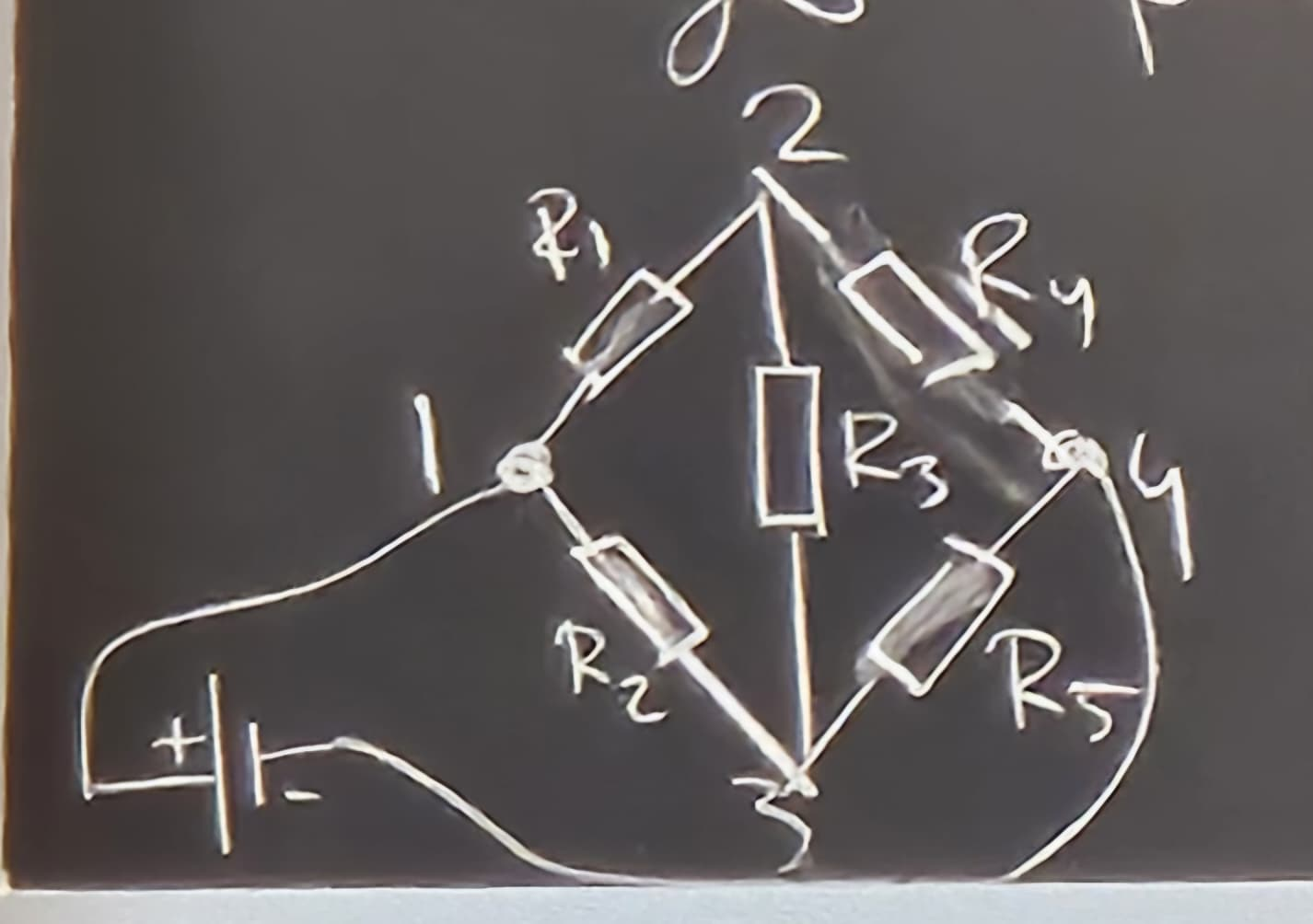
It has Kirchoff matrix
So
and
And with these you can calculate the effective resistance of the graph (though it is a little bit tedious)